Call : 08045479699
 Send Inquiry
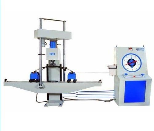
From our comprehensive collections testing equipment, we offer our esteemed clients highly efficient range of Leaf Spring Testing Machine. Our offered machine is designed and developed using optimum grade raw material and advanced technology as per the international standards. In order to ensure reliable performance and durability, this testing machine is tested on defined parameters by our adroit quality controllers. It is extensively demanded in the market due to its flawless finish, reliable performance, longer service life and easy maintenance.
Construction
Loading Frame
It consists of a base frame with cylinder and ram housed in it. The ball holder resting over ball seat in ram holds the crosshead, which contains two main nuts mounted in bearings and driven by a geared motor through chain & sprockets. Two main screws pass through the main nuts and are rigidly connected to the table to get the rapid adjustment of table for test height. A pair of trolleys roll the table smoothly.
Control panel
It is an assembly of following systems
Hydraulic System
The radial plunger pump, completely immersed in oil, is directly driven by a motor. All necessary accessories like oil filter, oil level indicator, air breather etc. are provided with this power pack unit. A pressure compensated needle type flow control Valve controls the oil flow to the main cylinder giving a non pulsating delivery of oil and the straining rate adjustable infinitely up to the maximum. Load Measuring System :-
The oil pressure in the main cylinder is transferred to the small dynamometer cylinder, the piston in which is kept rotating at a slow speed to ensure dynamic friction conditions. The piston exerts a force proportionate to the pressure on the hanger, which is transferred to the pendulum lever shaft through the auto load lever causing the pendulum lever to deflect. By auto load lever, the selection of range can be done by an external knob. An effective damping arrangement ensures slow return of pendulum if the specimen fails. Load Indicating System.
The deflected pendulum lever pushes a rack, which rotates a pinion engaging with it, which causes movement of pointer fixed to its shaft. The pointer moves with a dummy pointer on a large dial indicating the load and the dummy pointer retains the maximum reading after main pointer returns.
Autographic Recording System
A continuous roll type load deflection recorder is provided with the machine. The load is plotted on horizontal axis by the rack and the deflection is plotted on vertical axis. Deflection ratio of 1:2 and 1:5 can be selected.
Accuracy and Calibration
The machine is calibrated within an accuracy of 1% from 20% to 100% of the range as per IS 1828 and BS 1610.
Technical Specifications
| MODEL | STM-60 | STM-100 | FST-100 | FST-200 | FST-500 |
|
| 60 | 100 | 100 | 200 | 500 |
| 1st Range (kN) | 0-60 | 0-100 | 0-100 | 0-200 | 0-500 |
| Least Count (kN) | 0.1 | 0.2 | 0.2 | 0.4 | 1 |
| 2nd Range (kN) | 0-30 | 0-50 | 0-50 | 0-100 | 0-250 |
| Least Count (kN)Maximum Capacity (kN) | 0.05 | 0.1 | 0.1 | 0.2 | 0.5 |
| 3rd Range (kN) | 0-18 | 0-25 | 0-25 | 0-40 | 0-100 |
| Least Count (kN) | 0.03 | 0.05 | 0.05 | 0.08 | 0.2 |
| Table size (mm) | ---- | ---- | 250 x 2400 | 400 x 2400 | 460 x 2650 |
| Clearance for -compression test (mm) | 0-1250 | 0-1250 | 0-400 | 0-650 | 0-750 |
| Diatance between trolleys (adjustable) (mm) | ---- | ----- | 500-2150 | 650-2150 | 850-2300 |
| Ram stroke (mm) | 200 | 200 | 250 | 250 | 300 |
| Straining speed at no load (mm/min) | 0-200 | 0-125 | 0-250 | 0-150 | 0-100 |
| Pair of compression plates dia (mm) | 350 | 350 | 250 | 400 | 450 |
| Least Count of deflection measurement with DRO (mm) | 0.1 | 0.1 | 0.1 | 0.1 | 0.1 |
| Clearance between columns (mm) | 450 | 450 | ---- | ---- | ---- |
| Width of recorder chart (mm) | 150 | 150 | 150 | 150 | 150 |
| Connected load (HP) | 1.5 | 1.5 | 1.5 | 2 | 3 |
| Voltage (V) | 440 | 440 | 440 | 440 | 440 |
| Phase (Ph) | 3 | 3 | 3 | 3 | 3 |
 |
OM ENGINEERING INSTRUMENTS
All Rights Reserved.(Terms of Use) Developed and Managed by Infocom Network Private Limited. |
 English
 Spanish
 French
 German
 Italian
 Chinese (Simplified)
 Japanese
 Korean
 Arabic
 Portuguese